Category: plans (Page 1 of 2)

Heat recovery systems

One of the issues with modern buildings that are well insulated is air circulation.  There is a simple answer – open a window.  The only problem with this approach is that the heat from inside the building escapes with the air.

The solution is to install a heat recovery system that extracts the heat from the air in the building and uses this heat to warm up the incoming fresh air.  The system relies on a set of ducts to each of the rooms.  The level of air circulation can be varied room by room (for example, increased in bathrooms and kitchen).  One of the other advantages of a heat recovery is that it reduces internal condensation – even in shower rooms.

Usually, the ducting for the extraction and fresh air is installed in the loft space.  This may cause us an issue as there is no loft space in the new design building – the roof space is left opened up to reveal the king-post truss. 

The cost appears to be around £6,000 for the kit and the installation.

Villavent are one of the biggest vendors and you will find a useful video here on Youtube.

Update on the tender process

The deadline for the tender process for Phase 1 was yesterday. 3 out of the 5 companies that we sent the tender documents to have responded.  I am not sure if this is good or not, but the architect is trying to find out why two of the companies didn’t respond.  All had previously expressed an interest in doing the work.

The good news is that the three tenders that we have received are all within 10% of one another.

The quantity surveyor is now looking through each of the responses to make sure that the three tenders are for the same work.

Update on the tendering process

Having posted an entry stating that only 2 of the 5 companies that we sent tender documents to had arranged a site visit, a third company rang that morning.  The site visit was yesterday. So now 3 out of 5 have done a site visit. 

With the deadline for submission on Tuesday (7th May), it would seem unlikely that any more site visits are going to occur.  It will be interesting to see if we get quotes without the companies having done a site visit.  Still, we will know next week.

Phase 1 – now out to tender

A copy of the tender documents for Phase 1 (the re-roofing and refurbishment of the existing cottages) had arrived at home when I returned from London today.  This means that the companies tendering will also have received the documentation.

There is a lot of material here – all the work that needs to be completed has been itemised and there are a full set of building reg drawings.  I am glad that we are going out in 2 phases otherwise this pack of material would be enormous.

The deadline for responses is 7th May and we have suggested that if they want to a site visit that this should be organised via me for the week commencing 29th April (my first week off having finished work for a year!).

It feels like progress.

A 3D view…

3D artist’s impression of the renovations

The plans have now been submitted to the local planning department and although the 3D drawings are not part of the planning process, they do provide a clue to what the building will look like when finished.  You can see the main building is left pretty much as it is today (although minus the conservatory).  The barn on the end has become the corner of the L shape which is then extended out for the lounge and the master bedroom.

The roof line on the extension stays constant even though the ground rises upward.  The rooms inside flow when the natural rise in the land.  The garden area is split into two distinct spaces – a lower garden accessible from the lounge and a higher garden accessible from the master bedroom.  The roofline in the extension is at a lower level than the main house (pretty much as it is today) to give a clear separation between old and new.

So where is the well?

Apparently, none of the cottages were on the mains water supply until the 1970’s.  Until that point, water was collected from a spring 200m down the road using a barrel and a well barrow!  Seems a bit difficult to believe in this day and age when we take running drinking water for granted.

But there is something here that doesn’t stack up.  Why would someone in the 1750’s build three cottages where there was no water supply?  It is fairly common for old properties in the area to have their own well.  Often very deep – 40-50ft would not be unusual.  But there is no sign of a well on the property at all today.

So where might it have been?  I can’t imagine that it would have been at the rear of the property since there is no sign of any doors or access on that side.  I can’t imagine that it is going to be directly in front of the cottages as this area forms a sort of farmyard. The access has not changed over the years so it looks like it has always been a farmyard.

So the only other option is that it has to be located some where in the front of the property, beyond the farmyard, and in (what is now) the orchard.  But still no sign.  But it must be there somewhere.  Surely.

Dry stone walling – Day 3

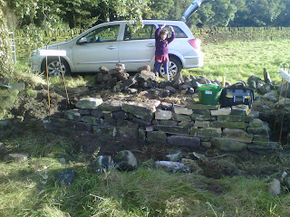
Well, it wasn’t really a whole day – just a morning as I got distracted.

I spent about 3 hours this morning dis-assembling and digging out the footings for another 2m stretch of wall.  I am being “less precise” with this stretch of the wall and doing the best I can with the current wall stone.  Yes, it is horrible and rounded, but for this field wall I am just going to have to do my best.  Shipping in huge amounts of new stone to build a field wall seems like a huge amount of wasted time and effort (not to mention money!).  I am hoping that by the end of this weekend that I will have at least part of the wall up to the finished height.  We will have to see.

Not much to look at for 2.5 days work.

I then faced two distractions in the afternoon.  Firstly, measuring out where the new extension will be and marking this out on the ground.  I haven’t got an electronic version of the plans, so haven’t had chance to post them here yet. Jo is concerned that you will be able to see into the master bedroom from the road.  I took the new plans that we have and used road pins to mark out where the master bedroom is going to be.  This was a useful exercise.  We now know that it will be very difficult to see into the bedroom from road level.  And if we are still in any doub, a small dry stone wall on the crest of the rise would totally block the view from the road.

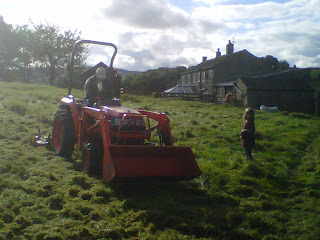
The second distraction was cutting the grass on the top field.  Rob kindly brought his tractor (and daughter – Ellie) to help with the job.  It took about an hour or so to cut the grass.  Strangely, it has a tendency to find all the stones in the field!  This slowed progress, but I now think that the majority of the loose stones have been removed.  We will have to see.  This is the last time that the field will have to be cut this year.


Rob showing the grass whose boss!
Rob and Ellie – Houston we have a problem!

The lower field has a lot more of slope, so the current plan is to graze some sheep in the lower field to get the grass down to more of a manageable level.  We just need to find out where we can borrow some sheep from!


Front elevations

Ok, so these are the front elevations – today and in May 1978 before it was converted from three properties into two.  I have included the rear elevations here.

You can quite clearly see where the old front door used to be for number 9 as well as the fact that new windows appear to have been added upstairs (as stated on the old plans).

The old plans were in a bit of a “distressed” state.  To view a larger image, just click on the picture.


Front elevation – today (above) and in 1978 (below)

Rear of the property

Well, we have been struggling to work out what the property used to look like in the past.  And now we know.  At least, what it looked like 34 years ago – in May 1978.  We have the architects drawings when the property was three separate cottages and before they were combined into two. The present owners found the plans when clearing out.

I have scanned in the architects drawings and matched them up with the recent elevations that we had done.  I have combined them in single images so that you can see the differences.  To view a bigger version, just click on the image itself.

Rear elevation: Today (above) and in 1978 (below)

The old drawings show that the ground level at the back of the property used to be just underneath window level at the back. This was reduced when the work was completed. We aren’t show if the conservatory was added at the same time.

Existing elevations

Here are the architect’s drawings of the elevations of the existing property.  I think they have done a great job, but there again I am always a sucker for these sort of engineering drawings!  You can zoom in by clicking on the images.

My hand drawings are elsewhere on the blog, so these just go to show how bad my drawings really are!  I didn’t want to publish any of this material until after we had completed on the purchase – it seemed to be tempting fate otherwise.


Front elevation
Front


Rear elevation
Back


Left hand end
Left hand end


Right hand end
Right hand end
« Older posts

© 2024 Hagg Leys Farm

Theme by Anders NorenUp ↑