Category: Layout

Dog shower

Although we installed this a few months ago, we have only just got around to installed the glass side to the dog shower.  The shower is in the boot room and intended for washing the dog and boots when the occasion calls.  It is a normal shower with a shower tray that has a silt trap. This is intended to stop the shower outlet from getting blocked up with mud off the dog or any wellies that get washed here.

The challenge was the glass side that was required for the side.  We didn’t want (or need) a screen that was full height.  However, we do need a screen to keep the water from the electric sockets that are close by.  The answer was to order some glass specifically for the job.  Probably is, it isn’t cheap.  We used 10mm glass that is tempered with polished edges and also has a radius on the top outer corner.  All of this pushes up the price.  This single piece of glass was around £150.  To make sure that the size was exactly right, we cut a template out of cardboard.  This enabled us to get the fit exactly right (as it turned out, the glass needed to be about 2mm out of square.  Because the glass is tempered, it cannot be cut locally.  It was ordered through Huddersfield Plate Glass who have provided us with our other glass and mirrors in the property.

To attached the glass to the wall, we used some specialist “U” channel.  This came with silicone seals and is made to fit 10mm glass. We had to cut it to length, but it does the job.  The metal strip is screwed to the wall and the glass simply pushes in.  The back of the “U” channel has clear silicone applied to it and there is also a layer of clear silicone holding the bottom of the glass against the shower tray.  The “U” channel had to be ordered.  It was supplied by Kudos shower accessories.  Cost was about £30.

The glass side has finally been installed.  The red patches need to be cleaned off once the silicone sealant has set.

The glass side has finally been installed. The red patches need to be cleaned off once the silicone sealant has set.

Here is a close of the "U" channel that has been used to attach the glass securely to the wall. This was supplied by Kudos shower accessories.  The channel comes with silicone seals that help firmly hold the glass in place.

Here is a close of the “U” channel that has been used to attach the glass securely to the wall. This was supplied by Kudos shower accessories. The channel comes with silicone seals that help firmly hold the glass in place.

The new kitchen

One of the things that has surprised me is that a number of decisions need to be made so quickly.  Here’s an example…..the kitchen.

The concrete slab has yet to be laid in the new extension.  This includes the slab for the kitchen.  You can see the current state of the build in the photo below.

The kitchen as it is today.  The two brown pipes are for the island unit.  The three brown pipes in the background are for waste from the sink and a pipe for the kitchen extractor.

The kitchen as it is today. The two brown pipes are for the island unit. The three brown pipes in the background are for waste and cold water for the sink and a pipe for the down draft extractor.

To be able to get the pipework in the right place in the concrete, we need to understand the layout in the kitchen.  We have really had to move quickly over the next few weeks and have just placed the order for the kitchen.  While the finishes may change, the layout is pretty set.  We have used the layout to define where the pipework should go in the concrete slab.

There is a 75mm layout of insulation to go on top of the slab and then another 75mm of screed.  The screed will contain the underfloor heating pipes.  You can put the water feeds into the insulation layer, however, we have put the cold water supply (blue pipe in the photo) inside a brown plastic waste pipe.  By putting the cold water supply into the concrete slab, we avoid the cold water from being warmed up by the underfloor heating.

I am sure that there will be a few more tweaks to come, but this gives an impression of what the kitchen should look like when finished.

I am sure that there will be a few more tweaks to come, but this gives an impression of what the kitchen should look like when finished.

The kitchen design has been done by KC Design in Clayton West – again, we are using another local firm.  The kitchen is bespoke and will be produced here in Yorkshire.  Now we have sorted out the layout, we can relax a little bit as it will be the back end of the year before we are ready to install it.  Lots of decisions to be made between now and then.

Kitchen and lounge floor plan

With Phase 2 of the construction fast approaching, it is time to start sorting out the details of how the roof trusses and internal windows are going to work.  Phase 2 is the building of an extension onto the existing property and will house the kitchen, lounge, master bedroom, two en suite bathrooms, a boot room and a utility room.

The roof line will be level, but because the ground rises up the inside ceiling height will decrease as you move through the extension.  The kitchen is double height, the lounge one and a half height and the bedroom normal height.  The roof trusses will be exposed as in the existing part of the property and there will be extensive use of roof lights.

The proposal is that the roof trusses will be made of oak and made in the same traditional way (tenon joints with oak pegs) rather than using any metal plates or straps.  There has been some debate about the exact placement of the beams and how “open” the space should be between the kitchen and the lounge.  We have opted for a semi-open approach with a large slot for a door way and another large opening behind the seating area.  The very last 3D drawing in this blog attempts to illustrate this.

The existing cottages are on the left and the new extension with lounge and master bedroom are directly in front of us.

The existing cottages are on the left and the new extension with lounge and master bedroom are directly in front of us.

The kitchen and lounge (but not the hall) are all in the new extension that is being built as part of the Phase 2 construction.

The kitchen and lounge (but not the hall) are all in the new extension that is being built as part of the Phase 2 construction.

Looking from the lounge into the kitchen.  The feature wall in the far wall in the kitchen will be built using stone that we have salvaged from demolition work elsewhere on site.

Looking from the lounge into the kitchen. The feature wall in the far wall in the kitchen will be built using stone that we have salvaged from demolition work elsewhere on site.

Existing elevations

Here are the architect’s drawings of the elevations of the existing property.  I think they have done a great job, but there again I am always a sucker for these sort of engineering drawings!  You can zoom in by clicking on the images.

My hand drawings are elsewhere on the blog, so these just go to show how bad my drawings really are!  I didn’t want to publish any of this material until after we had completed on the purchase – it seemed to be tempting fate otherwise.


Front elevation
Front


Rear elevation
Back


Left hand end
Left hand end


Right hand end
Right hand end

Existing floor plans

Since we bought the property before any estate agents details were produced, these are the first floor plans of the property that we have seen.  We have been working off some of the rough sketches that I did using Google Maps as a source for the overall size and shape of the property.


Ground floor floorplan
Ground Floor

You can see quite clearly the outline of the three original cottages with the middle one being smaller than the two adjoining.  Interestingly, this fact is also borne out by the census records that show that the middle property consisted of just two rooms – one up and one down.  These days it is difficult to imagine bringing up a family in such a property.


First floor floorplan
First Floor

I didn’t want to publish any of this information until we had exchanged – it seemed to be tempting fate otherwise.

The farm today (drawings)

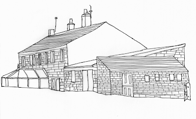
Here’s a couple of drawings of the farmhouse as it is today.  The second drawing shows the property in less detail, but labels up the different parts that go to make up the building.  You will find photos of the property here.

The cottages were originally three cottages (8, 9 and 10 Hagg Leys).  It was only in the 1990s that numbers 9 and 10 were converted into one property – known as 10 Hagg Leys today.  We plan to join all three cottages together and connect it to the barn.


Drawing of the existing properties
Drawing of the property today


The barn is a simple construction with a sloping corrugated roof.  There are two floor levels inside the barn.  The lower floor level is probably at about the same level as floor level inside the cottages themselves. The current plan is that the barn will form the corner of an extension that will be at a right angle to the existing cottages.  Thus forming an “L” shape.


Outline drawing of the existing properties
The different parts that make up the property


Attached to the barn is another building with a lean-to roof.  This time the roof is made up of stone tiles.  It is believed that this building was used to prepared food for animals.  For want of a better label, I have called this the “piggery” since we believe that the food prepared here was destined for pigs. This building is likely to be demolished as part of the renovation and wherever possible the materials reused elsewhere on the site.

How accurate is measuring using Google Maps?

Well, now I have an accurate set of floor plans, I can compare the estimates that I worked out using Google Maps (see previous post).

I estimated the overall size of the buildings (including the barn) to be around 20 feet by 80 feet.  The floor plans (and the topo survey) show that the building is in fact 22 feet by 82 feet.  Remarkably close to the Google Map estimate.  I tried a few other measurements that I had taken and they are all within about 10% of the actual measurement – this is particularly the case with longer measurements.  It is pretty scary about how much detail you can glean from these satellite images.

Using Google Earth to work out the layout of the property

One of the challenges with purchasing Hagg Leys Farm is that we do not have any property details.  We bought the property before the details had been produced and once the property had been sold, there was no interest in producing these.  So we are having problems answering basic questions such as “how many sq ft is the property?”, “How big is the garden?” etc.
As it turns out, the square footage is an important factor in estimating a number of the basic costs so it is important to be able to get an estimate of this, no matter how rough.  It occurred to me that Google Earth might be a good option here.  I zoomed in on the property as much as I could and grabbed the bitmap (using the snipping tool in Windows 7).  I then pasted this into PowerPoint and drew around the outline of the buildings including other features such as the access road and outbuildings.  You can then remove the underlining satellite image to reveal the outline of the property plan.
Two important things to remember.  Firstly, if you shrink the bitmap, make sure that you keep the proportions the same.  Secondly, when you grab the bitmap make sure that you include the scale.  If you do this, you should be able to mention the outline of the buildings.  Using this approach, I managed to estimate that the square footage of the existing building is around 2700 sq feet (excluding the unconverted barn). I could also start to building some outline designs for the renovation as well as calculating the potential increase in square footage.  I used this to provide some illustrations to the architect and it turned to be a really useful process.

© 2024 Hagg Leys Farm

Theme by Anders NorenUp ↑